2. How DVS Rectification Works
This chapter explains how lens distortion affects event coordinates and how those coordinates are corrected. It first models lens distortion, then calculates the original sensor coordinate corresponding to one corrected output position. For DVS data, it chooses the nearest integer pixel and stores that correspondence in a LUT for real-time use.
2.1 A real lens and sensor introduce geometric offsets
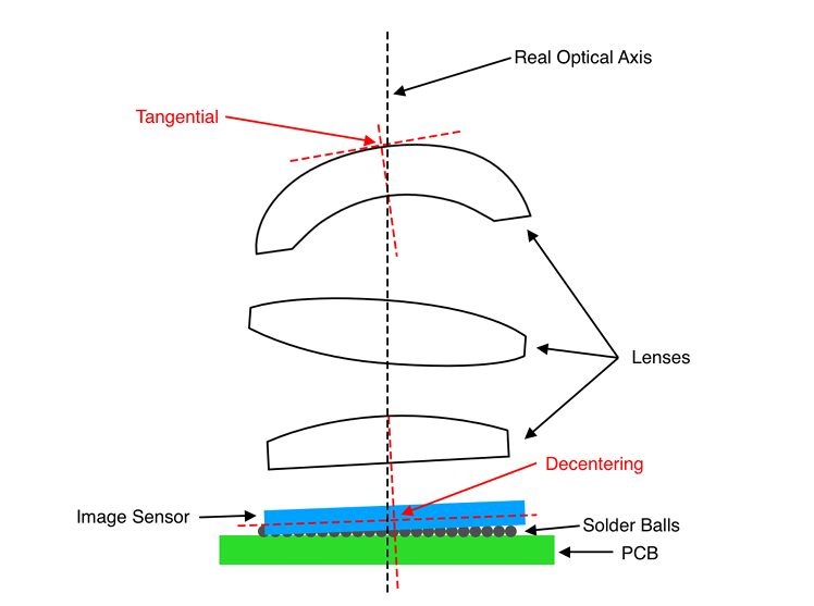
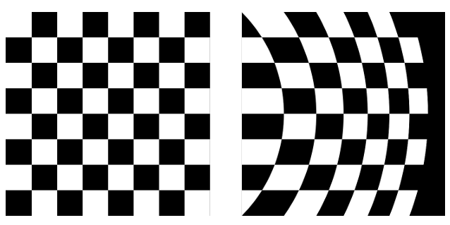
An ideal pinhole camera projects a scene ray to one predictable point on the sensor. A real camera uses several curved lens elements in front of a physical sensor. Lens curvature, assembly tolerance, slight sensor tilt, and a shift between lens and sensor centres make the observed coordinate differ from that ideal point.
The scene object does not move. Its sensor coordinate does. Calibration measures that difference for the individual camera so that Rectify can later apply the measured relationship to arriving events.
2.2 How distortion changes coordinates
Calibration does not choose a visual effect such as “barrel” or “pincushion.” It estimates coefficients that explain how this camera moves coordinates. The OpenCV model combines a radial term with tangential terms and, when present in the calibration, optional thin-prism terms.
2.2.1 Radial distortion
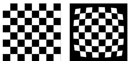
Radial distortion is centred on the optical centre and usually grows toward the image edge. It is why an otherwise regular grid may bow outward or inward. The rational radial scale L(r) expresses that centre-based change.
2.2.2 Tangential distortion
When the lens is tilted slightly or not perfectly centred over the sensor, the displacement is not rotationally symmetric. The tangential coefficients p1 and p2 represent that decentring effect in the coordinate model.
2.2.3 Optional thin-prism term
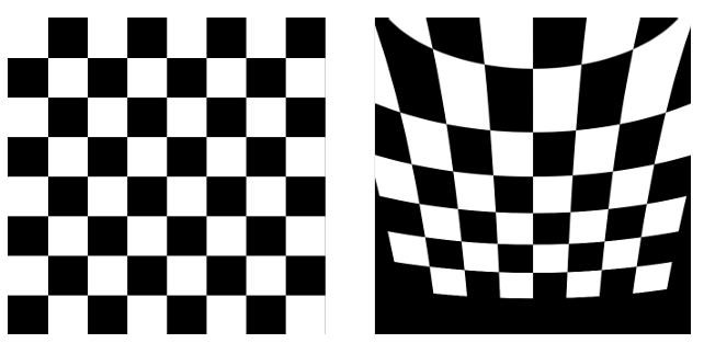
Depending on the distortion model, thin-prism coefficients s1 through s4 may be added. They represent residual asymmetric distortion caused by effects such as tilt between the lens and image plane, and Rectify applies them only when they are present in the calibration result.
2.3 Calculate the source sensor coordinate from a corrected output
Rectification starts with one corrected output coordinate (u, v), not with an input event pushed forward. The following calculation asks where the original sensor must be sampled to fill that corrected location.
Input: rectified output coordinate (u, v) → Output: source-sensor coordinate (us, vs)
x = (u − cx) / fx, y = (v − cy) / fy
The radial, tangential, and, when present, thin-prism terms described above are combined for one coordinate.
xd = xL(r) + Δxt + Δxs, yd = yL(r) + Δyt + Δys
us = fxxd + cx, vs = fyyd + cy
One corrected output coordinate (u, v) produces one source sensor coordinate (us, vs).
For a stereo camera, each camera’s lens-distortion correction is accompanied by Stereo Rectification, which uses the relative position and orientation of the left and right cameras. It aligns corresponding observations from the same scene as closely as possible to the same y coordinate, or epipolar line, in the two images. Stereo Matching can then search for correspondences mainly along the horizontal direction.
2.4 Use the nearest integer DVS pixel for a calculated source coordinate
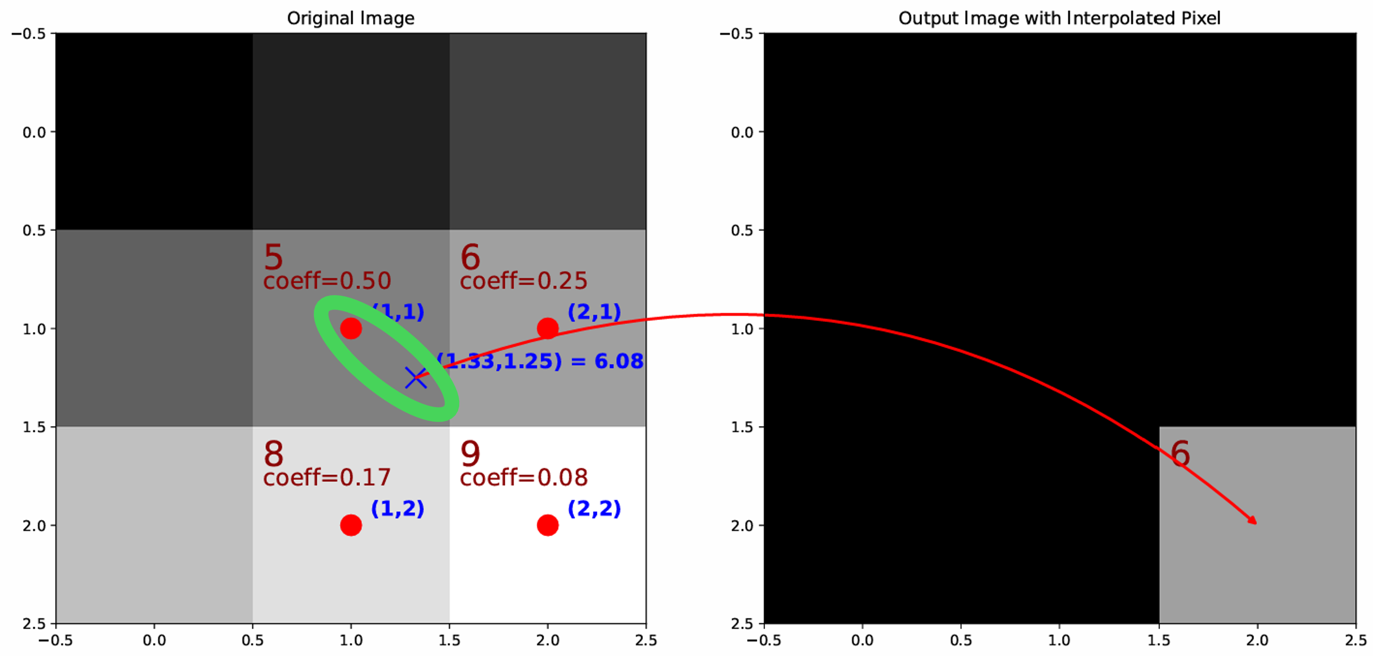
The calculated source coordinate may not be an integer. For example, a corrected output location may refer to (103.2, 198.7) on the original sensor. A conventional brightness image can interpolate nearby pixels to calculate a new intensity value.
A DVS event, however, is an ON, OFF, or absent state at one integer pixel. NRV Rectify does not mix neighbouring events. It selects the nearest integer coordinate—(103, 199) in this example—and keeps that location's event polarity.
2.5 Store the prepared coordinate relationship as a LUT
The corresponding relationship between each corrected output coordinate and its original sensor coordinate is prepared as a lookup table (LUT) during Setup.
calibration.yaml → Coordinate calculation → Coordinate LUTDuring live operation, Rectify looks up the prepared coordinate relationship instead of repeatedly evaluating the lens equations, then transforms each event location. Runtime output remains ordinary DVS packet data.
2.6 Valid ROI and final DVS output
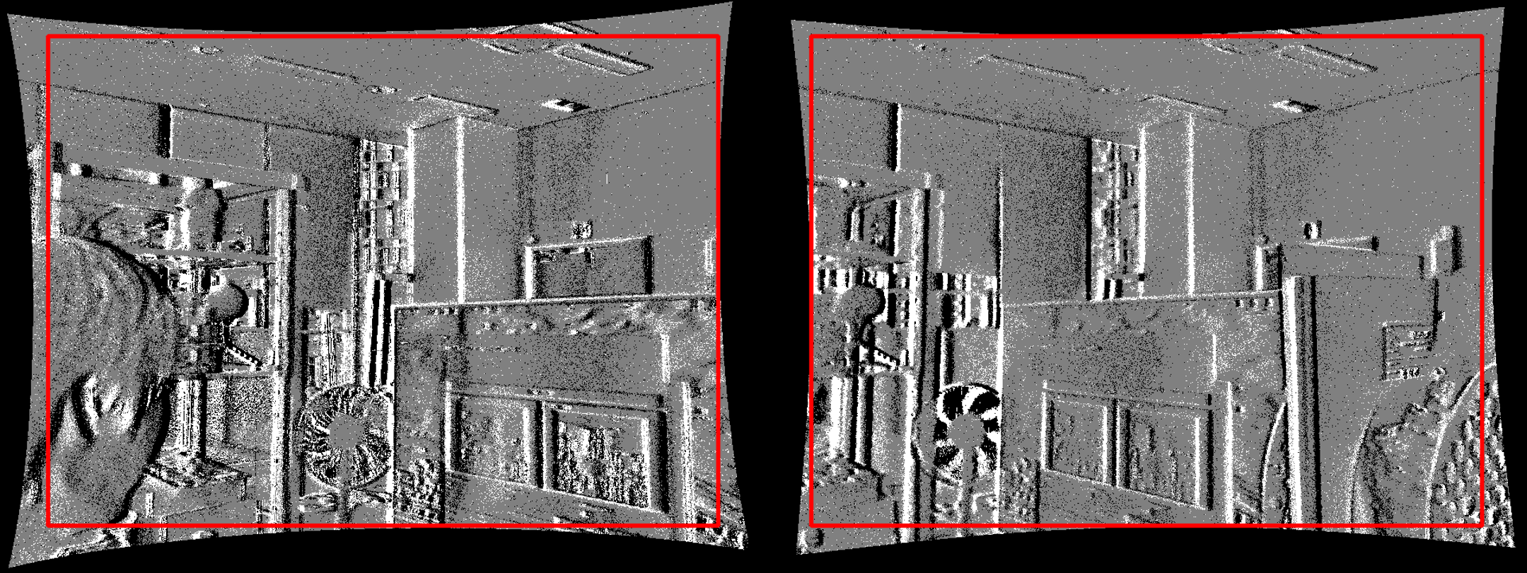
After coordinate correction, some output locations can refer outside the physical input sensor. There is no original event to read at those locations, so the final output retains only the valid region that has real source coordinates.
NRV Rectify retains the Valid ROI and does not enlarge it back to the original frame size.
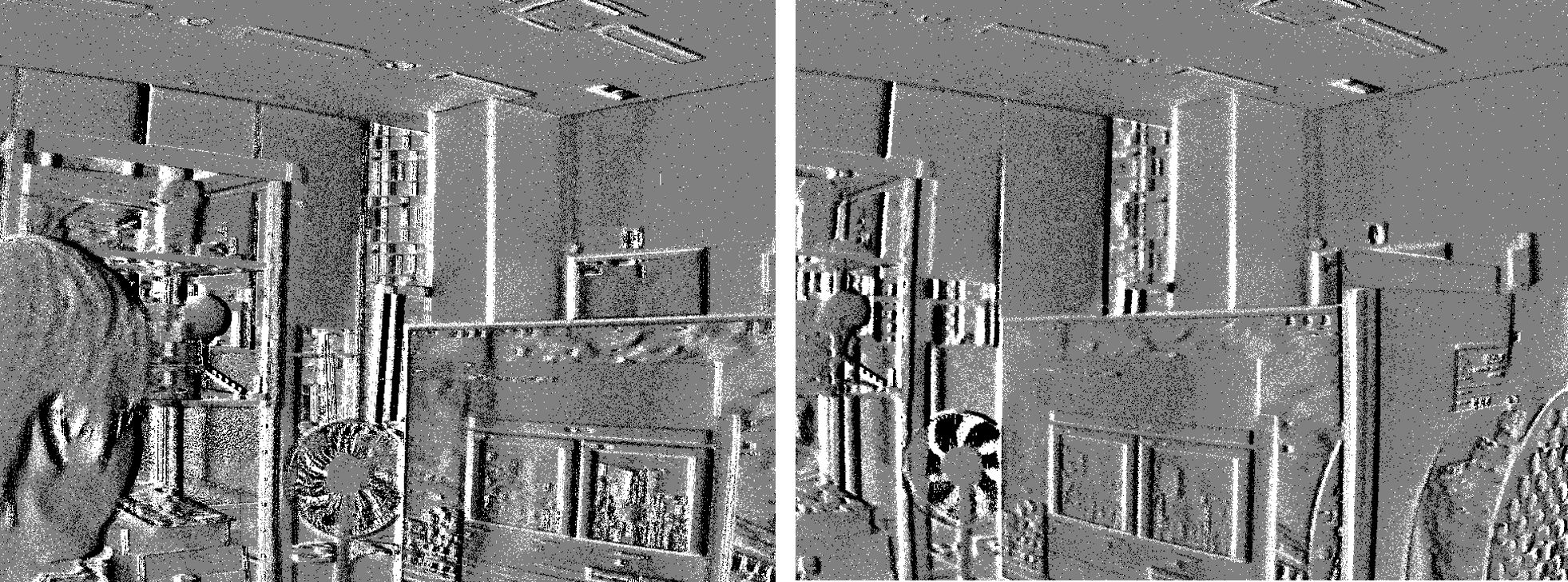
① Original DVS events
These are the original event coordinates with lens distortion still present.
② After coordinate correction
After the lens model corrects event coordinates, some edge locations can lie outside the original sensor area and cannot read a valid source event.
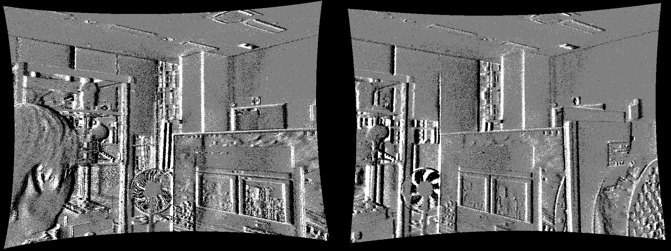
③ Valid ROI applied
Only locations that can refer to original events remain. This region is not enlarged back to the original resolution.