3. Capture Environment and Preparation
Clean NRV DVS calibration data starts with a stable capture environment. Before recording, prepare the NRV DVS, two monitor roles, software tools, pattern dimensions, and stable capture conditions so that the blinking circle grid is the dominant source of events.
3.1 Required Equipment
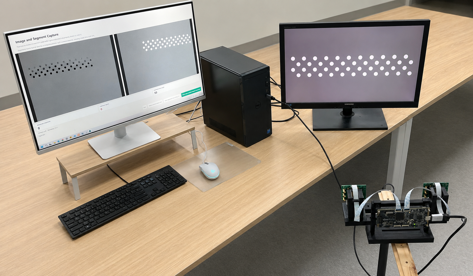
Prepare the following equipment before starting a mono or stereo capture. Each item has a specific role in keeping the target visible and the recorded event stream stable.
NRV DVS
Records ON and OFF events generated by the blinking target.
Camera Control PC
Connects to the camera and runs the recording software.
Camera Control Monitor
Shows camera connection, recording controls, and live event output.
Blinking Pattern Monitor
Acts as the calibration target by displaying the blinking circle grid.
Tripod or Fixed Camera Mount
Prevents camera movement and vibration during recording.
Ruler / Measuring Tool
Measures the physical spacing of circles on the target monitor.
Data Recording Software
Records the event stream used for later point selection and calibration.
Use it to operate the camera, start and stop recording, and inspect event output.
Use it only to show the blinking circle grid at full screen during capture.
A separate blinking pattern monitor is recommended. It allows the calibration target to remain full screen without camera controls, recording windows, or other UI elements covering the pattern.
3.2 Required Software Downloads
Download the pattern generator before capture. Calibration is not a separate program to download: it is entered from the Calibration button in DVS Viewer. Confirm that the installed Viewer includes that button; if it does not, obtain the Viewer version that includes Calibration. Chapter 4 explains the calibration workflow after entering from Viewer.
Blinking Circle Grid Generator
Displays the blinking asymmetric circle grid on the target monitor. The packaged Python script and usage instructions can be downloaded directly from this page.
Download Blinking Circle Grid Generator (.zip) ↓Calibration in DVS Viewer
Select Calibration in DVS Viewer to enter the calibration application. It records calibration segments, selects circle-grid inputs, and calculates mono or stereo parameters. The operating procedure is explained in Chapter 4, “Using the DVS Calibration App.”
Open nrvcorp/DVS_Viewer ↗3.3 Blinking Pattern Monitor Setup
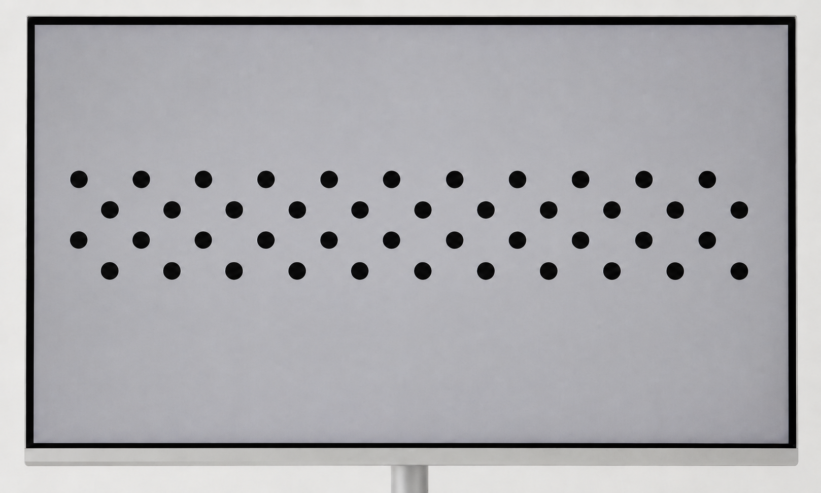
Treat the blinking pattern monitor as a physical planar calibration target. Configure the display first, then leave it fixed for the entire recording.
- Display the blinking circle grid in full screen.
- Use a flat monitor. A curved monitor does not represent the required flat target plane.
- Make sure no part of the pattern is clipped by the screen boundary.
- Adjust circle size and spacing until the NRV DVS event image clearly separates every circle.
- Keep the monitor stable throughout capture.
- Remove other windows, UI elements, notifications, and the mouse cursor from the pattern.
3.4 Measuring Circle Spacing
The calibration program requires the real physical distance between neighboring circle centers. This value is not the pixel spacing set in the pattern generator. Measure it on the actual monitor that will display the blinking pattern, because the physical size changes with monitor dimensions, resolution, and display scaling. If the calibration target changes, measure the spacing again for that specific monitor and setup.
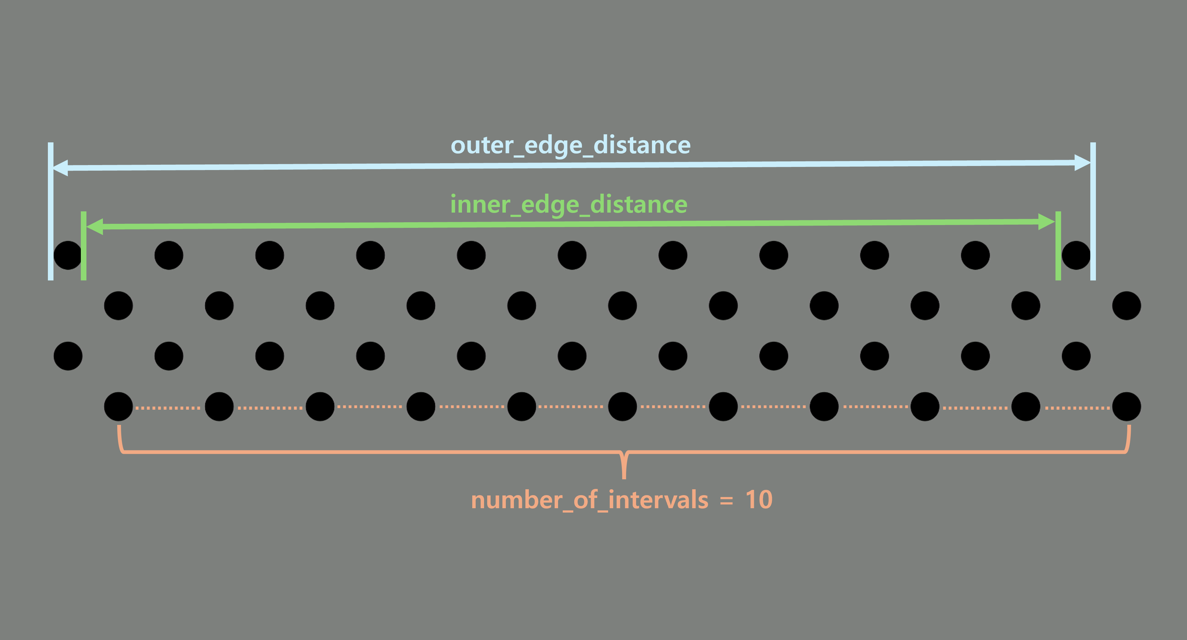
It is difficult to place a ruler exactly at the center of each displayed circle, and measuring only one interval makes small ruler errors relatively large. This guide measures across multiple intervals, averages the outer-edge and inner-edge distances, and then divides by the interval count. This reduces measurement error and gives a more reliable circle spacing value.
- 1
Display the blinking circle grid on the monitor that will be used as the calibration target.
- 2
Select the two outermost circles in the same row.
- 3
Measure the distance between the outer edges of those two circles.
- 4
Measure the distance between the inner edges of the same two circles.
- 5
Average the two measurements to estimate the center-to-center distance between the outermost circles.
- 6
Count the number of circle intervals between the selected circles.
- 7
Divide the center-to-center distance by the number of intervals.
- 8
Use the result as the circle spacing parameter in the calibration program.
3.5 Importance of Camera Fixation
During calibration capture, the NRV DVS should be fixed to a tripod or rigid mount. The goal of this step is not to test how well the system works during motion; it is to collect accurate reference data before later measurement or reconstruction steps.
Camera shake changes brightness across many image locations at once. This produces unnecessary events around the scene, can make the circles appear stretched or distorted, and makes center detection less stable than a stopped capture. For calibration, keep the camera, monitor, cables, and surrounding objects as still as possible so that most events come from the blinking circle grid itself.
An NRV DVS does not create conventional frame-based motion blur in the same way as a CIS camera, but small motion still changes the geometric projection. Rays from the monitor pixels can land on slightly different sensor pixels over time. Around each circle boundary, this small shift can spread the event cluster and negatively affect circle-center estimation.
It may feel natural to expect calibration to work while the camera is moving, but calibration is the reference step used to improve accuracy later. That is why the calibration data should be captured under controlled, stable conditions first.
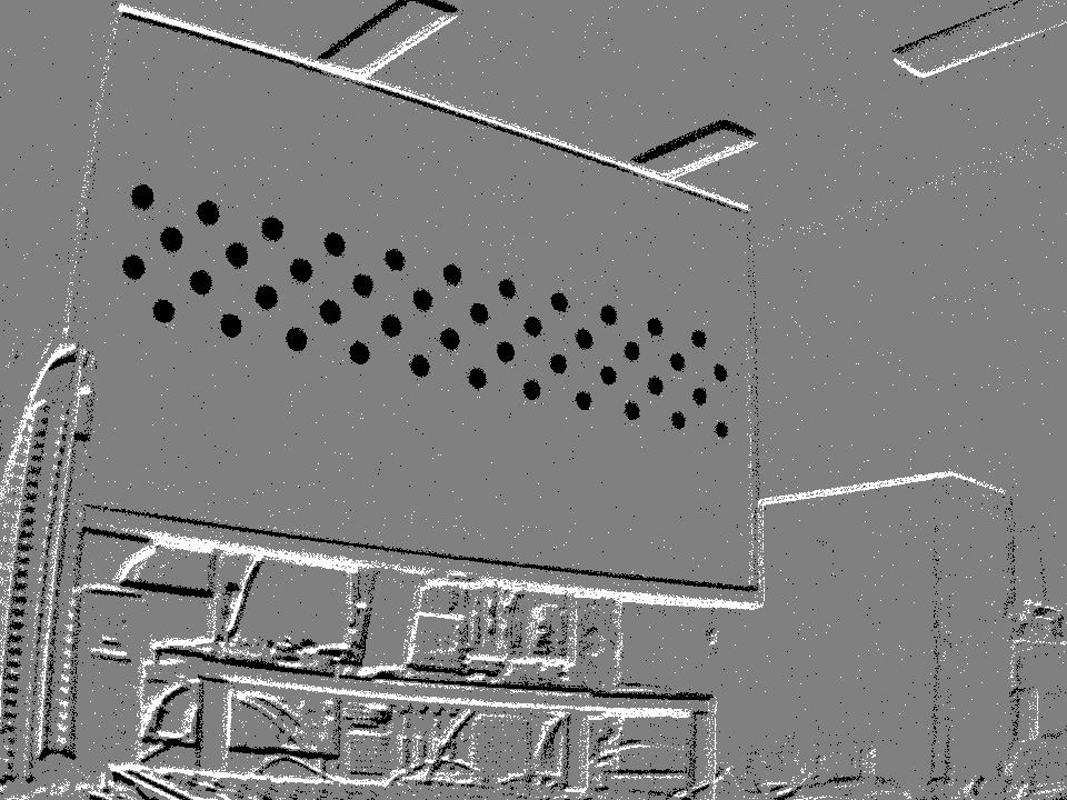 Unstable capture: surrounding scene events are mixed with the pattern.
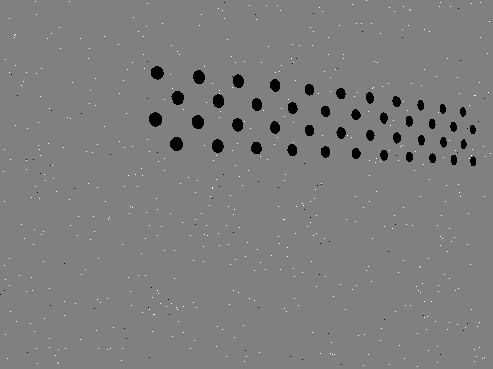 Fixed capture: the circle grid is isolated and easier to detect.
3.6 Recommended Calibration Capture Conditions
The blinking monitor is the fixed planar target for this procedure. Keep the monitor, the displayed pattern, focus, zoom, and sensor settings unchanged. Between segments, move the camera and its fixed tripod together so that the monitor grid occupies a different part of the sensor image, has a different distance, or has a different perspective. During one segment, neither the monitor nor the camera assembly should move.
One camera — mono calibration
| Monitor-grid coverage | At least 20% of the sensor image; aim for 50–80% when the full grid remains visible and unclipped. |
|---|---|
| Target angle | Include a near-front 0° view and left/right, up/down, and combined tilts of 15–45°. |
| Maximum tilt | Keep the monitor plane within about 45° of the camera plane so the grid remains reliably detectable. |
| Image position | Record centre, left, right, top, bottom, and all four corners. Do not repeat only central front-facing views. |
| Distance | Mix near, middle, and far positions around the intended operating distance. |
| Recorded segments | Record at least 20 geometrically different segments. Up to about 40 segments is recommended when they continue to add useful coverage. |
| Monitor target | Keep the whole asymmetric circle grid inside the image. Use the fixed flat monitor in full screen without windows or overlays. |
Two cameras — stereo calibration
| Coverage in each view | At least 20% in each camera; aim for 40–70% while the complete grid remains visible in both views. |
|---|---|
| Common observation | The same static monitor grid must be detected completely by the left and right cameras in the same recorded segment. |
| Angles and positions | Use 0°, 15–45° left/right, up/down, and combined tilts across the shared centre, sides, top, bottom, and edges of the two views. |
| Distance | Include near, middle, and far positions without changing the stereo baseline or the relative camera orientation. |
| Recorded pairs | Record at least 20 geometrically different stereo segments. Up to about 40 accepted pairs is recommended when both views remain valid. |
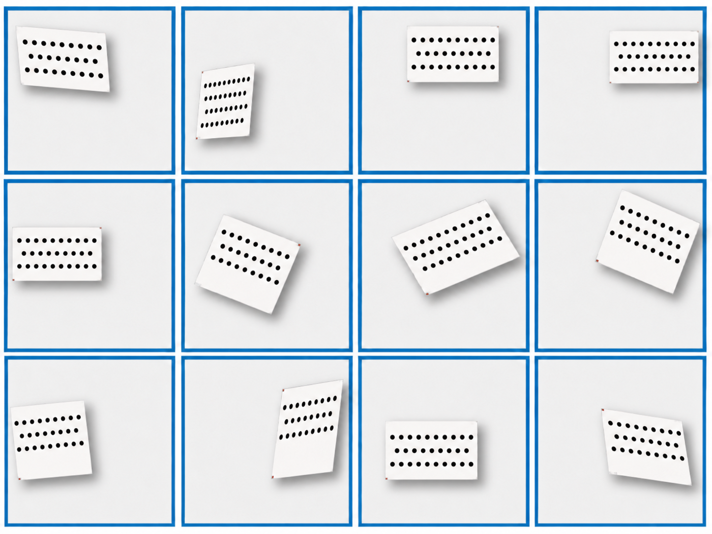 Record the monitor grid at several different poses, not only front-facing.
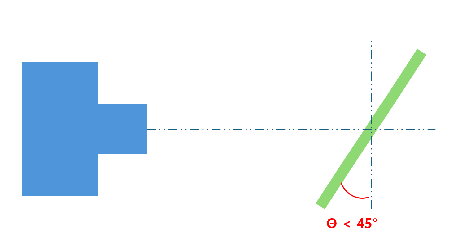 Use a front view and controlled tilts up to about 45°.
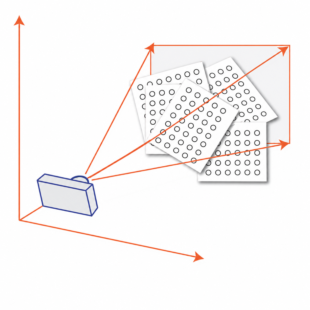 Fill centre, edges, corners, and multiple distances across the sensor area.
Start with at least 20 positions: three near-front views, four left/right tilts, four up/down tilts, four combined 30–45° tilts, and five edge or corner views. For stereo, apply the same plan only where the full monitor grid is visible in both cameras. Continue to about 40 recorded segments when each new pose adds useful coverage rather than repeating the same observation.
3.7 Capture Quality Checklist
Check the live event image and the physical setup before starting each recording.
- Is the full circle grid visible in the NRV DVS field of view?
- Are all circles clearly separated from each other?
- Are ON/OFF events generated clearly around the circle boundaries?
- Are there no clipped circles at the image boundary?
- Is the blinking pattern displayed on a flat monitor?
- Is the camera fixed without hand shake or vibration?
- Is the monitor stable and not moving during capture?
- Are surrounding objects kept still to avoid unnecessary events?
- Are hands, cables, or reflective objects removed from the camera view?
- Is the event image mainly generated from the blinking circle grid?
Once the capture environment is prepared, the next step is to follow the complete calibration workflow from pattern display to data selection and calibration computation.