2. NRV DVS Calibration Method
NRV DVS calibration has the same geometric purpose as conventional camera calibration: it estimates parameters that make image or event coordinates usable for measurement. The difference is how the calibration points are made visible to the sensor. An NRV DVS does not continuously output full brightness frames, so the calibration pattern must create brightness changes over time.
2.1 Difference from CIS Cameras
A CIS camera captures a full intensity image at each frame. Because the entire brightness image is available, a static checkerboard or circle grid can be detected directly from the image pattern.
An NRV DVS works differently. It does not continuously send complete intensity frames. Instead, each pixel reports an event only when the brightness at that pixel changes. A static calibration board may therefore produce little useful data for a NRV DVS, even if the pattern is clearly visible to a CIS camera.
For NRV DVS calibration, the calibration pattern must make the calibration points change over time. Those changes allow the NRV DVS to generate events at known pattern locations.
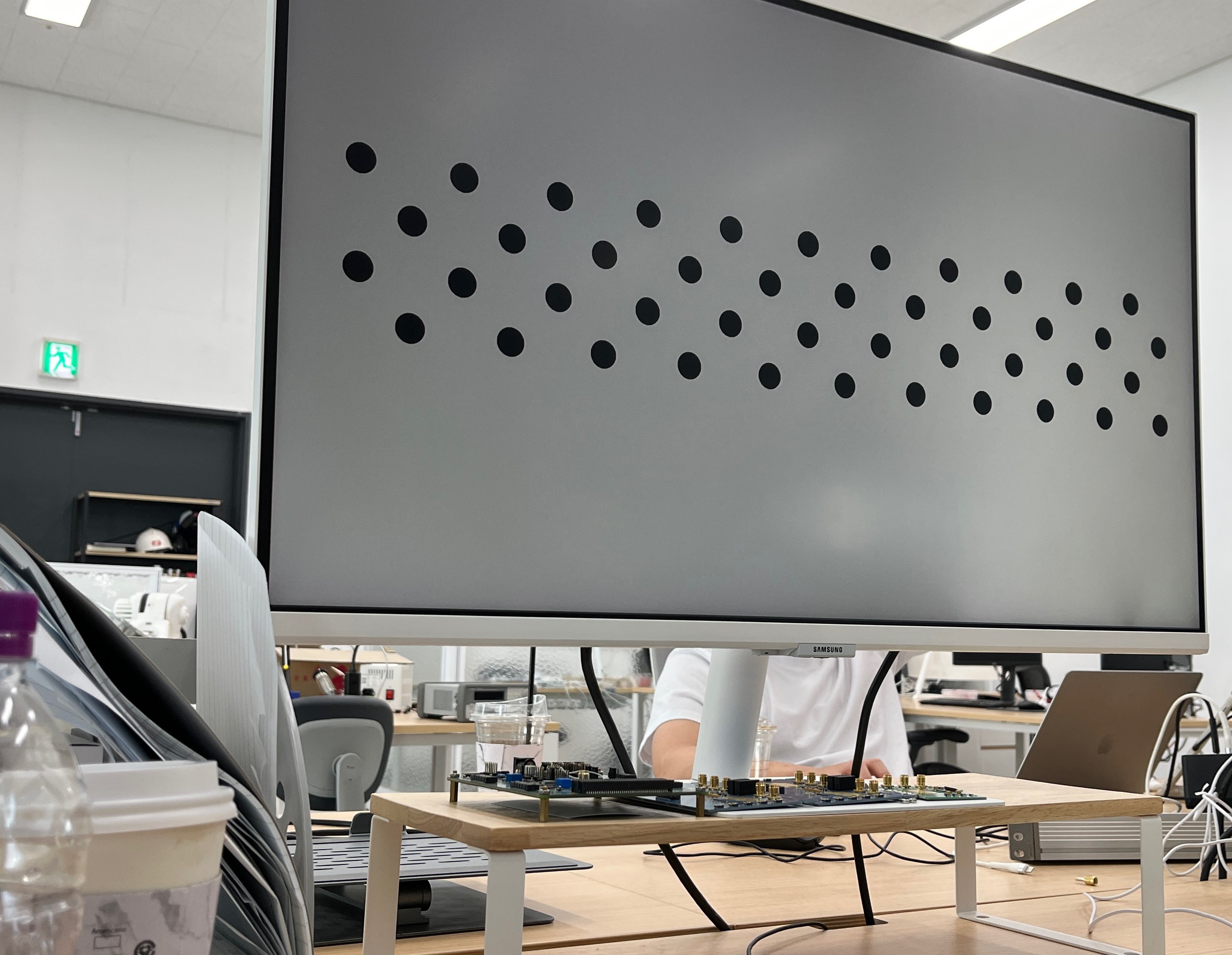 CIS: complete intensity frame
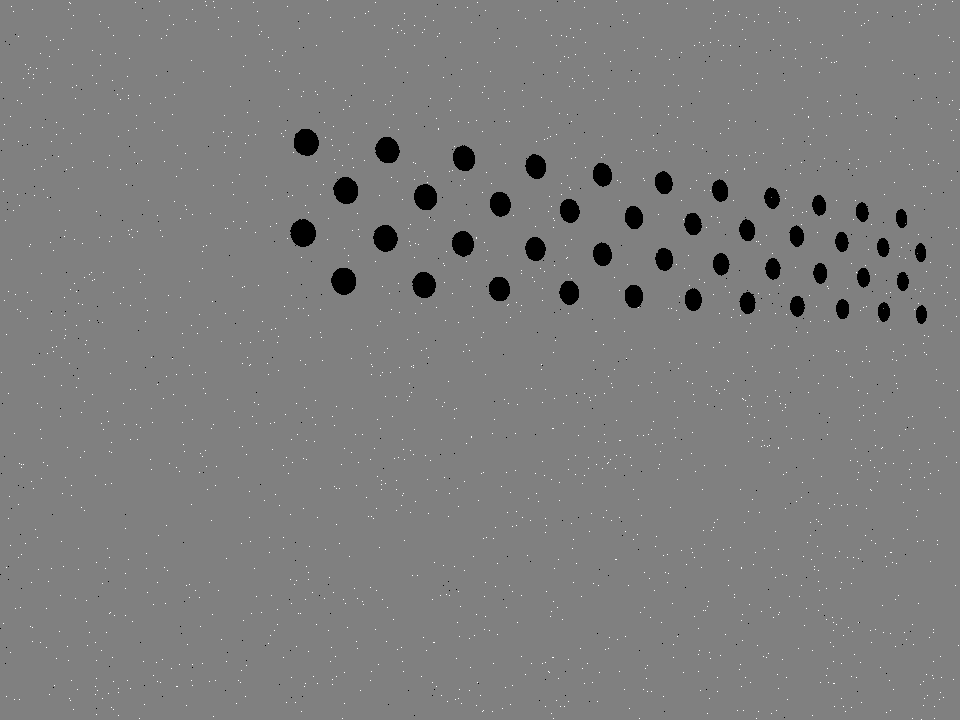 DVS: brightness-change events
2.2 Why Event Generation is Required
NRV DVS calibration needs clear ON and OFF events at known calibration point locations. A target should therefore blink, move, or change brightness over time. In this system, a monitor is used to display a blinking circle grid.
The circles alternate between bright and dark states. When a circle changes from dark to bright, the NRV DVS generates ON events around the circle boundary. When the circle changes from bright to dark, the NRV DVS generates OFF events. The purpose is to make the circle positions visible to the NRV DVS as reliable event data.
 Bright grid → ON events
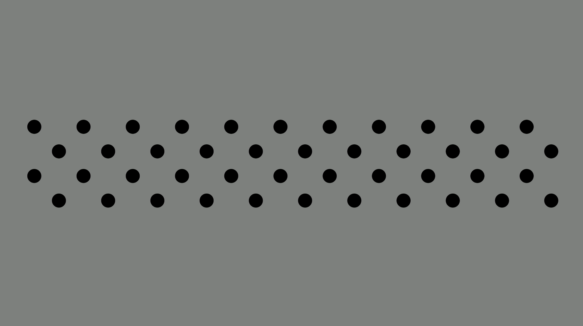 Dark grid → OFF events
2.3 Why a Blinking Asymmetric Circle Grid Is Used
An NRV DVS calibration target must be visible in event data, provide points whose centers can be measured reliably, and allow those points to be indexed in a consistent order. A blinking asymmetric circle grid is used because each part of the design addresses one of these requirements.
Blinking
Makes the pattern visibleBright-to-dark and dark-to-bright transitions deliberately generate OFF and ON events at known calibration point locations.
Circles
Makes each point measurableSeparated circle boundaries form local event clusters that can be grouped to estimate one circle center per calibration point.
Asymmetry
Makes point order identifiableAlternating row offsets give the grid a recognizable structure, allowing the detector to assign a consistent row and column order.
In short: blinking makes the target observable, circles make its points measurable, and the asymmetric layout makes their order identifiable.
Because the circles are spatially separated, events produced around one circle can be collected without mixing them with neighboring calibration points. The surrounding edge events provide enough geometric information to estimate the circle center. That center remains a well-defined feature when the target is viewed from different positions and angles.
A checkerboard corner is more difficult to recover from event data. Several black–white edges meet at the same location, so ON and OFF events from different edges can overlap or fragment around the intersection. Camera motion, brightness-change timing, and monitor refresh can then shift the apparent corner response. When a checkerboard is blinked on a monitor, the monitor does not always output the brightness transition as an ideal geometric corner at one exact instant, so the NRV DVS may record a smeared or broken corner response instead of a precise corner point. An isolated circle produces a simpler local event cluster and therefore a more reliable calibration point.
The asymmetric arrangement is also important. Adjacent rows are offset instead of forming a fully symmetric matrix. This gives the detector a recognizable layout for assigning point indices and reduces ambiguity when determining the grid's row and column structure.
Finally, displaying the pattern on a monitor makes the brightness transitions controllable and removes the need for a printed target or a separate blinking light source.
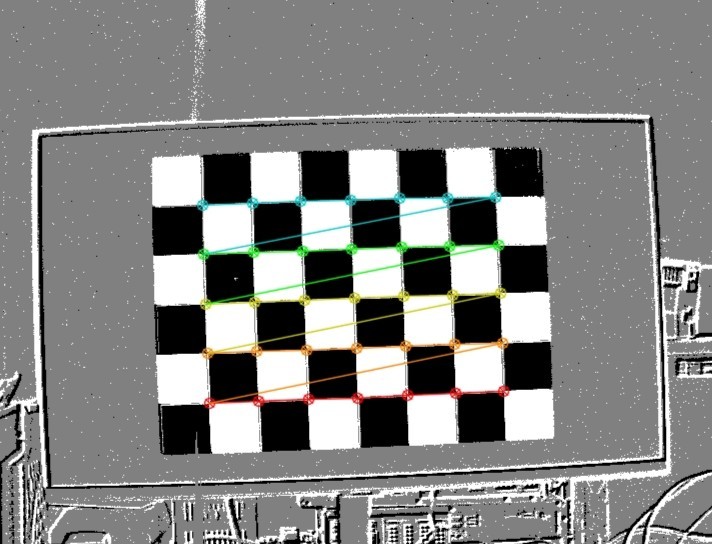 Checkerboard: corner events overlap
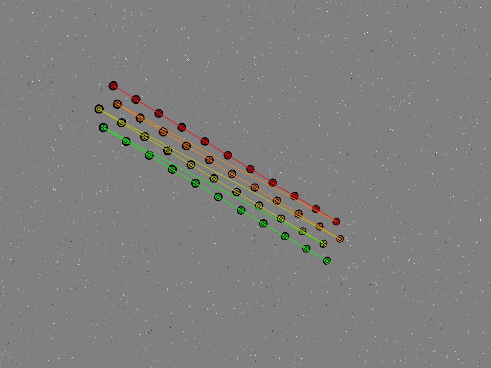 Circle grid: points stay separated
2.4 Calibration Pattern Configuration
The blinking asymmetric circle grid is displayed full screen on a monitor. The background is gray, and the circles toggle between bright and dark values. The asymmetric layout allows the calibration point order to be identified uniquely instead of being confused with a symmetric grid.
What is an asymmetric circle grid?
An asymmetric circle grid is a calibration target made of separated circular dots arranged in staggered rows. The calibration point is the center of each circle, so the detector does not need to rely on checkerboard corners where several edges meet.
In the generated pattern, the circle centers are evenly spaced within each row, and the row-to-row spacing is also defined consistently by the pattern. Because neighboring rows are shifted, the pattern direction is unique and the point order can be assigned reliably. For that reason, asymmetric circle grids are one of the common patterns used in camera calibration.
The number of rows, columns, circle spacing, and circle diameter must match the calibration program settings. The pattern should also be large enough for the NRV DVS to separate each circle clearly.
As an example, the reference repository uses 11 columns and 4 rows, a gray background, bright circles with value 255, dark circles with value 0, and blinking by toggling the circle color over time. These values are not mandatory. They can be adjusted depending on monitor size, camera distance, and the calibration setup.