DVS Bring-Up Project 1-2. Single DVS(SD Card Boot)
While functionally identical to DVS Bring-Up Project 1. AXIS Streaming Example, this project boots the ZCU106 from a SD card, simplifying PCIe connection process. It will show you how to boot the Xilinx Zynq Ultrascale+ ZCU106 from SD, while being connected to a host PC via PCIE interface.
Table of Contents
- Document History
- Introduction
- Configuring the ZCU106 for SD Card Boot
- (Optional) Generating BOOT.BIN from Vitis
- (Optional) Firmware Code Explanation
Document History
| Date | Version | Author | Description of Revisions |
|---|---|---|---|
| December 19, 2024 | 1.0 | Soosung Kim | Xilinx Zynq Ultrascale+ ZCU106 SD Card Boot Manual |
Introduction
ZCU106 Evaluation Platform
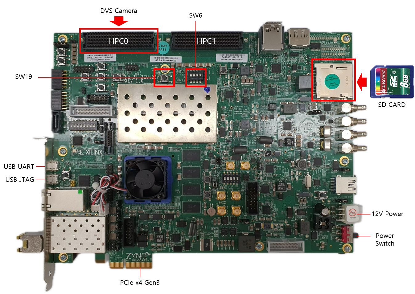
According to the PCIe installation manual, each reprogramming of the board requires rebooting the host PC and loading the Xilinx XDMA drivers. Additionally, the board's firmware code must be executed after each host PC reboot. Booting the board from an SD card can streamline this process by initiating the firmware code through an onboard GPIO button press. The following steps explain how to boot the ZCU106 board from an SD card and reconfigure the Vitis project for SD card boot functionality.
Key Features
- Works out-of-the-box: Operates independently without Vitis Project or Serial Terminal integration.
Configuring the ZCU106 for SD Card Boot
Prerequisites :
- A host PC that underwent the PCIe installation manual.
- A Zynq Ultrascale+ ZCU106 board connected with the host PC via PCIe.
- An empty SD card.
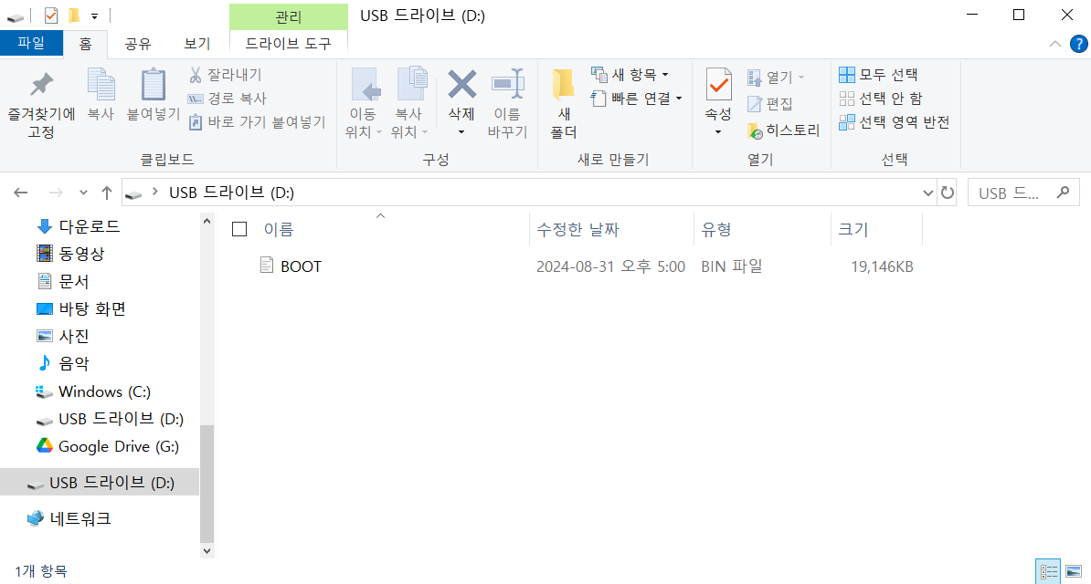
1) Download the example BOOT.BIN.
2) Place it in the SD card file system.
3) Turn the host PC and ZCU106 board off.
4) Plug the SD card in the ZCU106. Connect the DVS sensor to HPC0 FMC.
5) Set the boot mode switch SW6 to ON-OFF-OFF-OFF to SD boot mode as shown in the following figure.
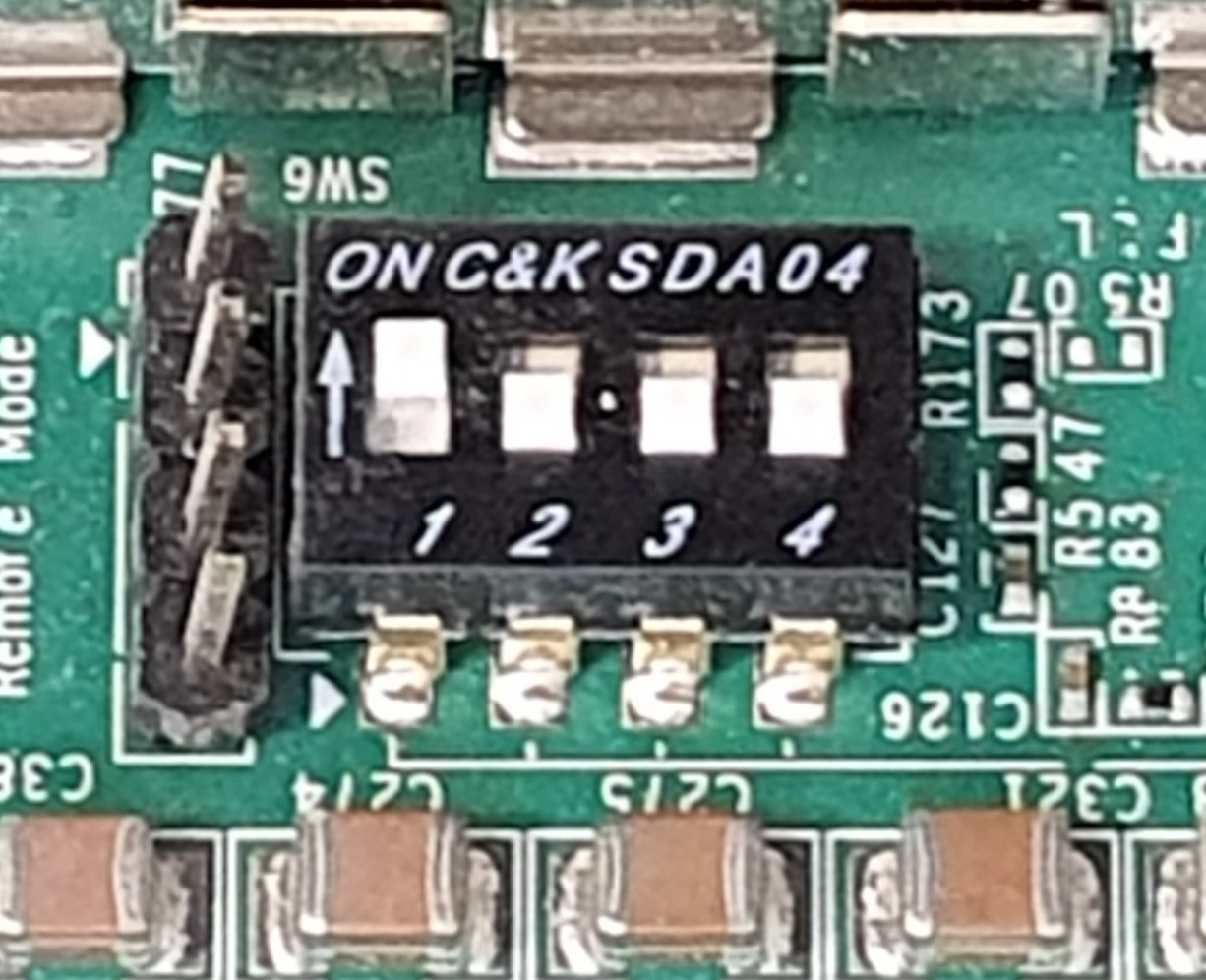
Note : For JTAG boot, set all 4 switches to ON.
6) Turn the board on, and check if the status LEDs are all green. Note : If not, the ZCU106 board might be broken.
7) Turn the host PC on, and verify the PCIe connection.
8) Press SW19 on the board to initiate firmware code execution.
9) Run host applications provided in the embeddedsw repository.
(Optional) Generating BOOT.BIN from Vitis
Building a Vitis Application Project will automatically generate a BOOT.BIN that can be used immediately.
Prerequisites :
- Vitis 2021.2
1) Download the example XSA file. .
2) Launch Vitis 2021.2, and select a workspace.
3) Select File > New > Application Project.
4) Select Next > Create a new platform from hardware(XSA).
5) Browse and select the XSA file from 1.
6) Click Next, and type the application project name <project_name_system>.
7) Click Next > Next, select Empty Application(C), and Finish.
8) From the explorer, navigate to <project_name_system>/<project_name>/src. Copy and paste Firmware code inside the directory.
9) From the explorer, right-click <project_name_system>, and click Build Project.
10) Navigate to <project_system_name>/Debug/sd_card.
11) Copy the BOOT.BIN to your SD card.
(Optional) Firmware Code Explanation
The following code, largely taken from a Xilinx example, polls on the PS GPIO to stall firmware code until a button press is detected.
To execute your custom firmware code after rebooting the host PC, you can copy and paste the following code to your custom Vitis project.
Polling Part :
u32 InputData;
//Polls on PS GPIO until SW19 is pressed
Status = GpioPolledExample(XPAR_PSU_GPIO_0_BASEADDR, &InputData);
if (Status != XST_SUCCESS) {
  printf("GPIO Polled Mode Example Test Failed\r\n");
  return XST_FAILURE;
}
// detects SW19 Button Press
printf("Data read from GPIO Input is  0x%x \n\r", (int)InputData);
// Proceeds to execute rest of the code
Function Declarations :
//GPIO poll example
static u32 Input_Pin; /* Switch button */
static u32 Output_Pin; /* LED button */
XGpioPs Gpio;

static int GpioInputExample(u32 *DataRead)
{

 /* Set the direction for the specified pin to be input. */
 XGpioPs_SetDirectionPin(&Gpio, Input_Pin, 0x0);
 /* Read the state of the data so that it can be  verified. */
 do{
  *DataRead = XGpioPs_ReadPin(&Gpio, Input_Pin);
  if(*DataRead==0x1) break;
 }while(1);


 return XST_SUCCESS;
}
int GpioPolledExample(UINTPTR BaseAddress, u32 *DataRead)
{
 int Status;
 XGpioPs_Config *ConfigPtr;
 int Type_of_board;

 /* Initialize the GPIO driver. */
 ConfigPtr = XGpioPs_LookupConfig(BaseAddress);
 Type_of_board = XGetPlatform_Info();
 switch (Type_of_board) {
  case XPLAT_ZYNQ_ULTRA_MP:
   Input_Pin = 22;
   Output_Pin = 23;
   break;

  case XPLAT_ZYNQ:
   Input_Pin = 14;
   Output_Pin = 10;
   break;

 }

 Status = XGpioPs_CfgInitialize(&Gpio, ConfigPtr,
           ConfigPtr->BaseAddr);
 if (Status != XST_SUCCESS) {
  return XST_FAILURE;
 }

 /* Run the Input Example. */
 Status = GpioInputExample(DataRead);
 if (Status != XST_SUCCESS) {
  return XST_FAILURE;
 }

 return XST_SUCCESS;
}