CIS_DVS with NPU Project 1. NRV Demo
This project serves as a demonstration platform showcasing the capabilities of NRVCORP architecture. It integrates multiple modules for a comprehensive test environment. Specifically, it receives data from the DVS sensor, analyzes it to obtain ROI bounding boxes, and crops CIS input frames for putting into the NPU. The detection results are shown on top of the original CIS video stream. For hardware demonstration, 2 boards are required : one board to run CIS_DVS, and one board to run our custom NPU.
Table of Contents
- Document History
- Introduction
- Download and Installation
- Project Build Steps
- Hardware Deployment Steps
Document History
| Date | Version | Author | Description of Revisions |
|---|---|---|---|
| December 4, 2024 | 1.0 | Soosung Kim | First MIPI2PCIE_AXIS Example Design of ZCU106 |
Introduction
ZCU106 Evaluation Platform
The ZCU106 MIPI2PCIE_AXIS Example Design uses the following IPs along with the Zynq UltraScale+ Processing System for demonstrating Video Streaming using mipi_rx_subsystem block made by our company.
- Zynq UltraScale+ MPSoC Processing System (Xilinx IP)
- MIPI D-PHY (Xilinx IP)
- mipi_rx_subsystem (NRV IP)
- DMA/Bridge Subsystem for PCI Express (Xilinx IP)
- AXI IIC (Xilinx IP)
- AXI GPIO (Xilinx IP)
Our Environment Setting is as follows :

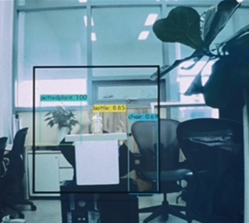
Below is an example image showing the results of moving object detection, where the black box is the ROI detected by DVS.
Key Features
- Multi-Module Integration: Combines CIS, DVS, and NPU datapaths together.
- Visualization Tools: Provides real-time monitoring and analysis specialized for motion detection in static environments.
- Extensive Testing: Includes pre-configured scenarios such as small object detection or dark environments for validation.
Download and Installation
- Install Vivado 2021.2, Vitis 2021.2 from Vivado Design suite.
- Clone the embeddedsw repository to your host PC.
- On the host PC, follow the PCIe installation manual.
Project Build Steps
1) Download the example XSA file.
2) Launch Vitis 2021.2, and select a workspace.
3) Select File > New > Application Project.
4) Select Next > Create a new platform from hardware(XSA).
5) Browse and select the XSA file from 1).
6) Click Next, and type the application project name <npu_project_name_system>.
7) Click Next > Next, select Empty Application(C), and Finish.
8) From the explorer, right-click <npu_project_name_system>, and click Build Project.
9) Follow the Project Build Steps for CIS_DVS, if you haven't done them already. The project name will be referred to as <cis_dvs_project_name_system>.
Hardware Deployment Steps
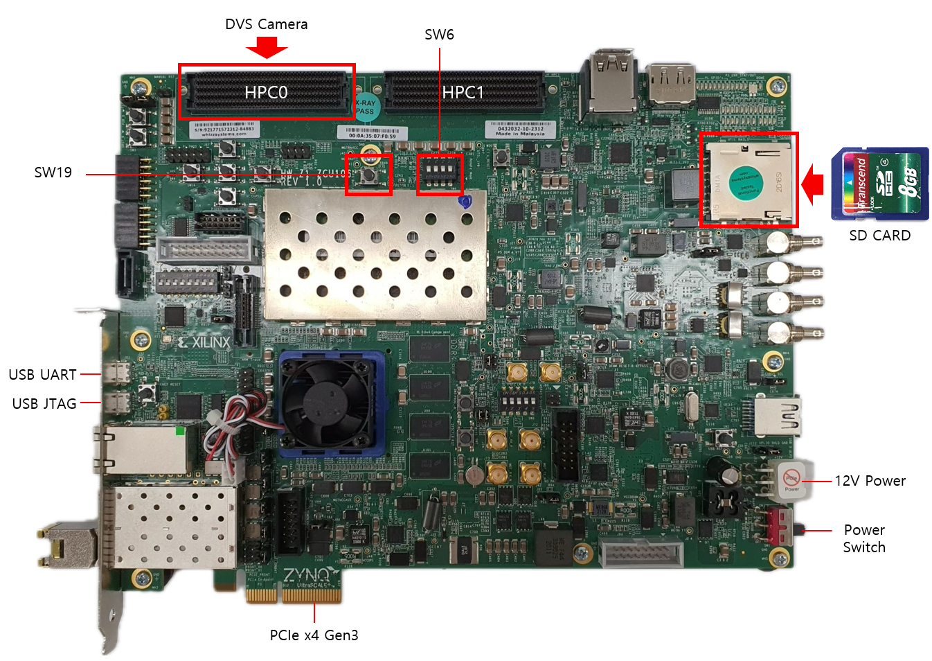
You need to prepare 2 ZCU106 boards, both connected to the host PC via PCIe.
- The first board, called the CIS_DVS board, should have CIS connected to FMC HPC0, and DVS connected to FMC HPC1.
- The second board, called the NPU board, runs our custom NPU.
Program the NPU board
1) Connect the NPU board's JTAG & UART ports with the host PC, and turn the board on.
2) On the host PC, open GTKterm and select Configuration > Port. Select /dev/ttyUSB0 or /dev/ttyUSB1, which should be the serial connection to the ZCU106.
3) From the Vitis Explorer, right-click <npu_project_name_system>, and click Run As > Launch Hardware.
4) Wait till the programming bar shows up, and the GTKterm shows a response message. If it doesn't, change ports and repeat the previous steps.
Program the CIS-DVS board
1) Unplug jtag and uart ports, and transfer cables to the CIS_DVS board.
2) From the Vitis Explorer, right-click <cis_dvs_project_name_system>, and click Run As > Launch Hardware.
3) Check if GTKterm displays any message, such as Is the camera sensor connected? (Y/N). If it doesn't, change ports and repeat the previous steps.
Rebooting for PCIe to recognize ZCU106 boards
1) Reboot the host PC. It must have XDMA drivers auto-running after each boot - refer to link
2) On the host PC, open GTKterm and select Configuration > Port. Select /dev/ttyUSB0 or /dev/ttyUSB1, which should be the serial connection to the ZCU106. Try pressing y in the window, and see if the serial window responds. If not, change ports and try again.
3) Verify the PCIE connection by following instructions (link). ls /dev should return xdma_dvs0 for the CIS_DVS board, and xdma_zcu1060 for the NPU board.
4) Run host applications provided in the embeddedsw repository.
Here are some reference materials you might find useful: