CIS_DVS Bring-Up Project 2. Spatial Filter
The CIS-DVS Concurrent Read project enables concurrent streaming of data from both sensors. By taking advantage of DVS's high frame rate and stability over varying environments and CIS's high resolution and color, it can analyze target scenes quickly and accurately while preserving the resolution and dynamic capabilities. By applying a spatial filter over the DVS frames, noise from the DVS sensor can be effectively filtered out, enhancing the accuracy of the basic CIS_DVS pipeline. It is optimized for noise reduction and improves data quality by processing events spatially.
Table of Contents
- Document History
- Introduction
- Download and Installation
- Project Build Steps
- Hardware Deployment Steps
1. Document History
| Date | Version | Author | Description of Revisions |
|---|---|---|---|
| December 4, 2024 | 1.0 | Soosung Kim | First CIS_DVS Example Design of ZCU106 |
2. Introduction
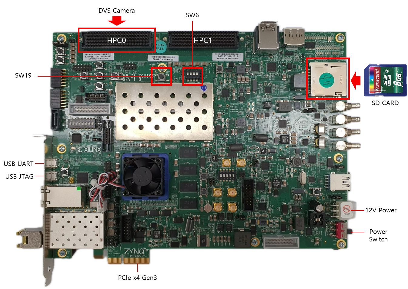
[ZCU106 Evaluation Platform]
The ZCU106 CIS_DVS streaming Example Design with Spatial Filtering uses the following IPs along with the Zynq UltraScale+ Processing System for demonstrating Video Streaming using mipi_rx_subsystem block made by our company.
- Zynq UltraScale+ MPSoC Processing System (Xilinx IP)
- MIPI D-PHY (Xilinx IP)
- mipi_rx_subsystem (NRV IP)
- Spatial Filter(NRV IP)
- DMA/Bridge Subsystem for PCI Express (Xilinx IP)
- AXI IIC (Xilinx IP)
- AXI GPIO (Xilinx IP)
- Sensor Demosaic (Xilinx IP)
- Gamma LUT (Xilinx IP)
- Video Processing Subsystem (Xilinx IP)
[LI-IMX274MIPI-FMC]
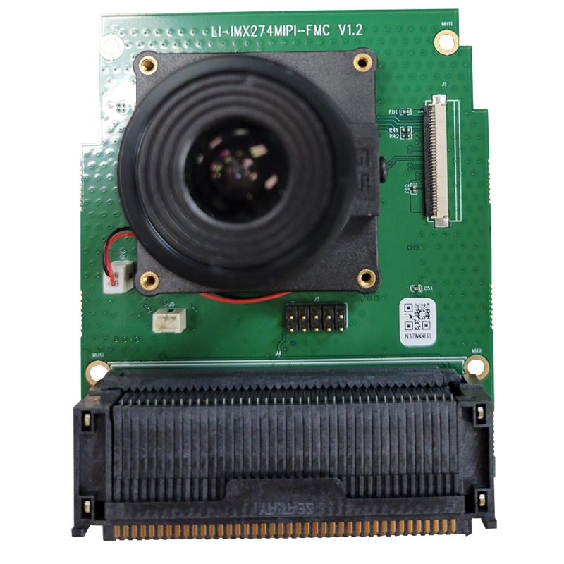
The ZCU106 CIS_DVS streaming Example Design uses LI-IMX274MIPI-FMC for the CIS camera. Cis Camera Vendor Link
Key Features
- Noise Filtering: Reduces unwanted noise from DVS event streams.
- Customizable Filters: Supports parameter tuning for different environments.
- Integrated Pipeline: Works seamlessly with the CIS_DVS setup.
3. Download and Installation
Prerequisites:
- Install Vivado 2021.2, Vitis 2021.2 from Vivado Design suite.
- Clone the embeddedsw repository to your host PC.
- On the host PC, follow the PCIe installation manual.
4. Project Build Steps
1) Download the example XSA file to be added here.
2) Launch Vitis 2021.2, and select a workspace.
3) Select File > New > Application Project.
4) Select Next > Create a new platform from hardware(XSA).
5) Browse and select the XSA file from 1.
6) Click Next, and type the application project name <project_name_system>.
7) Click Next > Next, select Empty Application(C), and Finish.
8) From the explorer, navigate to <project_name_system>/<project_name>/src. Copy and paste Firmware code inside the directory.
9) From the explorer, right-click <project_name_system>, and click Build Project.
5. Hardware Deployment Steps
1) While the ZCU106 is off, connect the CIS sensor to HPC0, and the DVS sensor to HPC1.
2) Connect the board's JTAG & UART ports with the host PC, and turn the board on.
3) On the host PC, open GTKterm and select Configuration > Port. Select /dev/ttyUSB0 or /dev/ttyUSB1, which should be the serial connection to the ZCU106.
4) From the Vitis Explorer, right-click <project_name_system>, and click Run As > Launch Hardware.
5) Check if GTKterm displays any message, such as Is the camera sensor connected? (Y/N). If it doesn't, change ports and repeat the previous steps.
6) Reboot the host PC. It must have XDMA drivers auto-running after each boot - refer to link
7) On the host PC, open GTKterm and select Configuration > Port. Select /dev/ttyUSB0 or /dev/ttyUSB1, which should be the serial connection to the ZCU106. Try pressing y in the window, and see if the serial window responds. If not, change ports and try again.
8) Verify the PCIE connection by following instructions (link).
9) Run host applications provided in the embeddedsw repository.
Here are some reference materials you might find useful: