DVS Bring-Up Project 1-1. Single DVS(AXIS Streaming Example)
This project showcases the high-frame-rate streaming capability of DVS sensors by transmitting data over a PCIe interface for display on a host PC. The architecture employs AXI-Stream to deliver frames to a Xilinx XDMA IP, which then streams the data to the host PC. Using Memory-Mapped I/O, the host PC continuously reads each 960x720 frame from a fixed base address, achieving a frame rate of 2000fps or higher. Additionally, the project supports two boot methods: the traditional JTAG boot as well as an SD card boot option, allowing the ZCU106 to boot directly from the SD card without requiring JTAG programming or a serial connection.
Table of Contents
- Document History
- Introduction
- Download and Installation
- Project Build Steps
- Hardware Deployment Steps
Document History
| Date | Version | Author | Description of Revisions |
|---|---|---|---|
| December 4, 2024 | 1.0 | Soosung Kim | First MIPI2PCIE_AXIS Example Design of ZCU106 |
Introduction
ZCU106 Evaluation Platform
The ZCU106 MIPI2PCIE_AXIS Example Design uses the following IPs along with the Zynq UltraScale+ Processing System for demonstrating Video Streaming using mipi_rx_subsystem block made by our company.
- Zynq UltraScale+ MPSoC Processing System (Xilinx IP)
- MIPI D-PHY (Xilinx IP)
- mipi_rx_subsystem (NRV IP)
- DMA/Bridge Subsystem for PCI Express (Xilinx IP)
- AXI IIC (Xilinx IP)
- AXI GPIO (Xilinx IP)
Key Features
- AXI Integration: Converts MIPI streams to AXI-Stream format for PCIe communication.
- High Throughput: Handles large data volumes with minimal latency.
- Scalable: Supports multi-lane MIPI configurations.
Download and Installation
- Install Vivado 2021.2, Vitis 2021.2 from Vivado Design suite.
- Clone the embeddedsw repository to your host PC.
- On the host PC, follow the PCIe installation manual.
Project Build Steps
Option 1 : JTAG BOOT
1) Download the example XSA file.
2) Launch Vitis 2021.2, and select a workspace.
3) Select File > New > Application Project.
4) Select Next > Create a new platform from hardware(XSA).
5) Browse and select the XSA file from 1).
6) Click Next, and type the application project name <project_name_system>.
7) Click Next > Next, select Empty Application(C), and Finish.
8) From the explorer, navigate to <project_name_system>/<project_name>/src. Copy and paste Firmware code inside the directory.
9) From the explorer, right-click <project_name_system>, and click Build Project.
Option 2 : SD CARD BOOT
Building a Vitis Application Project will automatically generate a BOOT.BIN that can be used immediately.
Instead of 8. and onwards of the above section, execute the following:
8) From the explorer, navigate to <project_name_system>/<project_name>/src. Copy and paste Firmware code inside the directory.
9) From the explorer, right-click <project_name_system>, and click Build Project.
10) Navigate to <project_system_name>/Debug/sd_card.
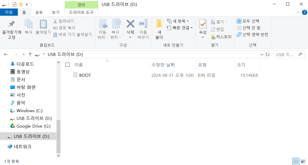
11) Copy the BOOT.BIN to your SD card.
Hardware Deployment Steps
Option 1 : JTAG BOOT
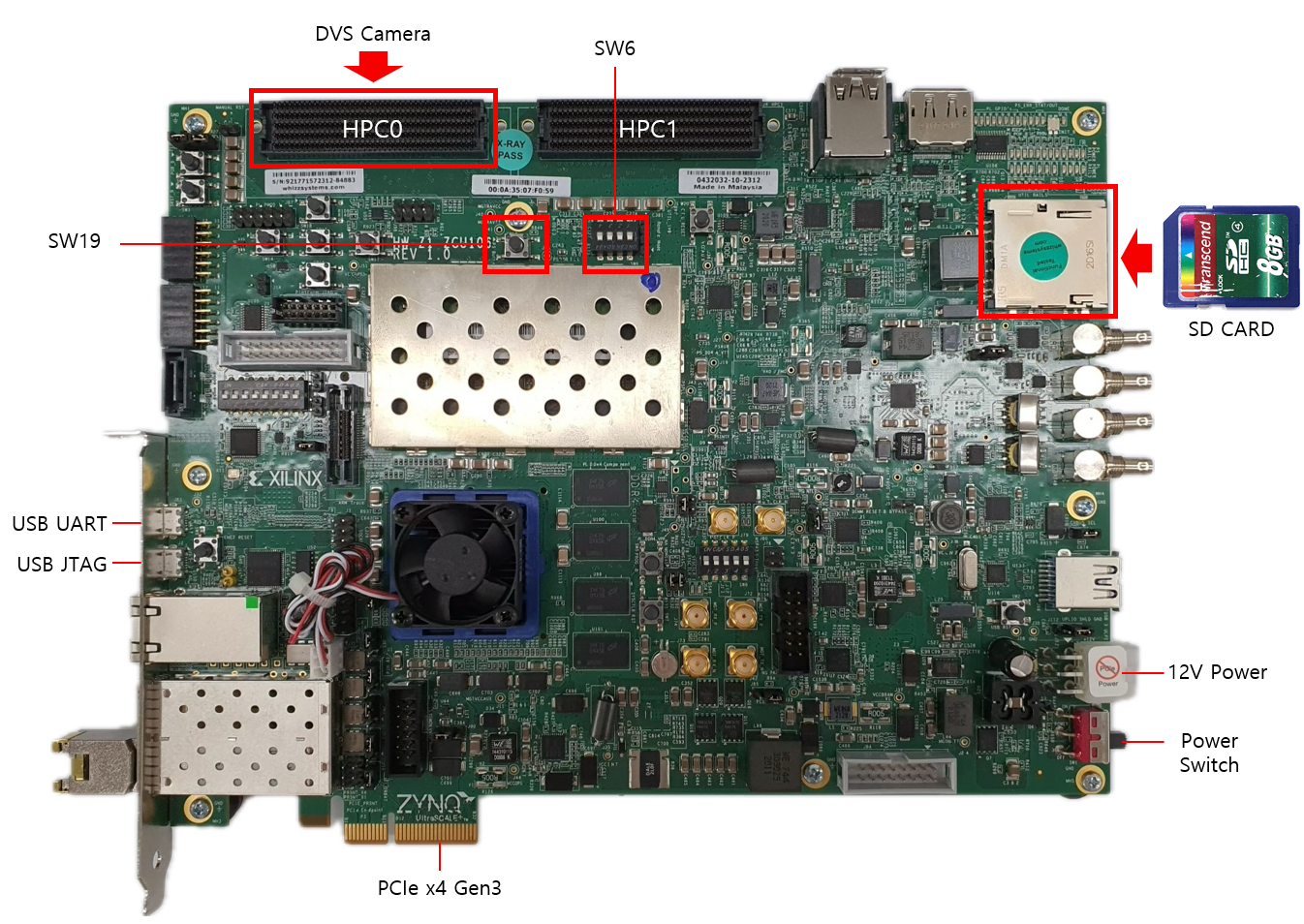
1) While the ZCU106 is off, connect the DVS sensor to HPC0.
2) Connect the board's JTAG & UART ports with the host PC, and turn the board on.
3) On the host PC, open GTKterm and select Configuration > Port. Select /dev/ttyUSB0 or /dev/ttyUSB1, which should be the serial connection to the ZCU106.
4) From the Vitis Explorer, right-click <project_name_system>, and click Run As > Launch Hardware.
5) Check if GTKterm displays any message, such as Is the camera sensor connected? (Y/N). If it doesn't, change ports and repeat the previous steps.
6) Reboot the host PC. It must have XDMA drivers auto-running after each boot - refer to link
7) On the host PC, open GTKterm and select Configuration > Port. Select /dev/ttyUSB0 or /dev/ttyUSB1, which should be the serial connection to the ZCU106. Try pressing y in the window, and see if the serial window responds. If not, change ports and try again.
8) Verify the PCIE connection by following instructions (link).
9) Run host applications provided in the embeddedsw repository.
Option 2 : SD CARD BOOT
1) Download the example BOOT.BIN. You can also use the BOOT.BIN you copied to your SD card.
2) Place it in the SD card file system.
3) Turn the host PC and ZCU106 board off.
4) Plug the SD card in the ZCU106. Connect the DVS sensor to HPC0 FMC.
5) Set the boot mode switch SW6 to ON-OFF-OFF-OFF to SD boot mode as shown in the following figure.
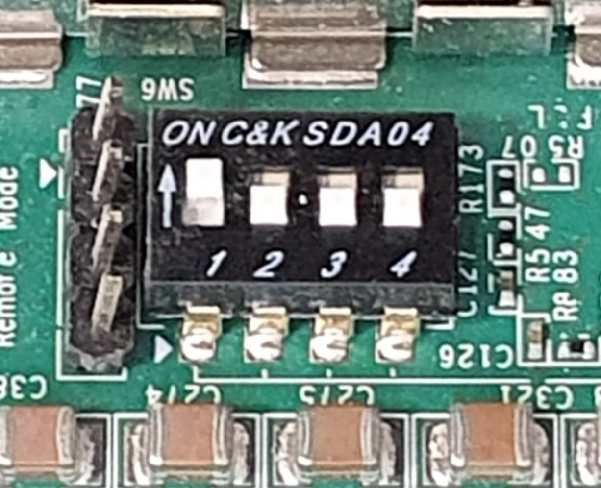
Note : For JTAG boot, set all 4 switches to ON.
6) Turn the board on, and check if the status LEDs are all green. Note : If not, the ZCU106 board might be broken.
7) Turn the host PC on, and verify the PCIe connection.
8) Press SW19 on the board to initiate firmware code execution.
9) Run host applications provided in the embeddedsw repository.
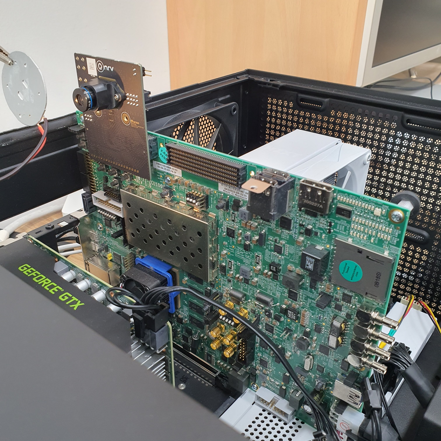
Below figure shows the complete board setup.
Below are DVS images taken from a cooler fan. Letters on the fan blades can be observed, although the fan is spinning.
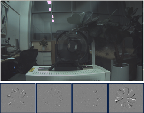
The video will appear as follows:
Here are some reference materials you might find useful: